Relay Coordination Study and Analysis
Product Details:
X
Product Description
RELAY COORDINATION STUDY AND ANALYSIS
In power system protection relay and circuit breakers is the major instrument for large interconnected power system. We need proper protection to isolate the faulted region from healthier network. When two protective apparatus installed in series have certain characteristics, which provide a specified operating sequence, they are said to be coordinated or selective. Relay coordination is an important aspect in the protection system design as coordination schemes must guarantee fast, selective, and reliable relay operation to isolate the power system faulted sections.
WHY IS RELAY COORDINATION STUDY AND ANALYSIS PERFORMED?
Relay coordination study and analysis is performed to make sure that safety operation of the system are functioning correctly and to avoid the nuisance tripping, as protection is a major concern in any industry and they rely on protective devices for the same. The reason for nuisance tripping is modification of protective devices and their settings at the time of upkeep without performing suitable study and analysis.
The aim of a coordination study is to determine the characteristics, ratings, and settings of overcurrent protective devices which will ensure that minimum unfaulty load is interrupted when protective devices isolate a fault or overload anywhere in the system. A coordination study should be conducted
- In the early planning stages of a new system to tentatively select protection and utilization equipment
- In the case where an existing system is modified and new loads are installed
- When existing equipment is replaced with higher rated equipment
WHAT IS DONE DURING A RELAY COORDINATION STUDY AND ANALYSIS?
ANSI / IEEE Std. 242 1986 (Recommended Practice for Protection and Coordination of Industrial and Commercial Power System) is the standard used for this study.
Mostly relay coordination study and analysis is computer aided. There are several computer programs available for the protection coordination analysis of power system applications. Such programs include short circuit analysis and device time current characteristics. The main purpose of the protective coordination software is to produce one-line diagrams, calculation of relay settings and time current coordination drawings. Software will contain features to model various protective devices, equipment damage curves and store the data for future use. Using the software, the device characteristics can be called from the library and used for the coordination studies.
- Personal computer either stand alone or connected to a network with sufficient memory is needed for this type of application. Also, a good graphical monitor and laser quality printer is required. By performing the study on a personal computer, several alternatives can be examined before arriving at the final solution. The data can be stored in the computer for future use or verification of the calculations. The one-line drawings, TCC and the output can be printed for a report. Alternatively, these files can be copied and pasted in word processing documents.
- Graphical display The one-line diagram of the electrical circuit and the device coordination curves can be displayed on the graphical monitor for demonstration. Such a display helps to identify the necessary corrections to be performed before getting a printout of the diagrams or graphs.
- One-line diagram A one-line diagram of the electrical circuit for which the coordination is performed is always needed for report preparation. The software can be used to prepare the one-line diagram with the necessary devices shown. Such an approach eliminates the need to deal with the drawing office support for the protection study.
- Project data files A database is a method of storing digital data. The database can be structured to store all the necessary device characteristics, short circuit data and coordination data. These programs can perform calculations of the inrush current, device settings and project details. The project data can be copied from one computer to another for analysis.
- Device library These programs are equipped with a large library of data from various manufacturers. The library includes models for overcurrent relays, ground relays, static trip breakers, moulded case circuit breakers, data for cable damage curve, and data for transformer damage curve, motor overloads and reclosers.
- Interactive data entry It is not always possible to have the data available from the device library for the selected study. If the data are not available and if the equation or graphical data are available, then the data can be entered interactively. The data points can be entered item by item and can be saved for future use.
HOW IS RELAY COORDINATION STUDY AND ANALYSIS DONE?
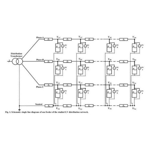
ONE-LINE DIAGRAM
If the study is on a new system or already existing system, attain or create a one- line diagram of the system or the part of the system concerned. The diagram should show the following data:
- Apparent power and voltage ratings as well as the impedance ratings and connections of all transformers.
- Normal and emergency switching conditions.
- Nameplate ratings and sub-transient reactance of all major motors and generators as well as transient reactance of synchronous motors and generators, plus synchronous reactance of generators.
- Conductor sizes, types, and configurations.
- Current transformer ratios.
- Relay, circuit breaker and fuse ratings, characteristics, and ranges of adjustment.
SHORT CIRCUIT STUDY
Obtain or perform a complete short-circuit study providing momentary and interrupting ratings. It must also contain highest and lowest anticipated fault interrupting duties, as well as inputs from every single short-circuit current source. Gather time–current characteristic curves for each protective device under consideration.
CURRENT SCALE SELECTION
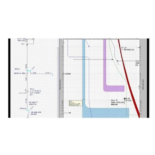
Because the whole aim of the study is to attain time-sequenced tripping of overcurrent protective equipment, the characteristic curve of the device closest to the load is plotted as far to the left of a 4- by 4-cycle graph as possible so that the source side characteristic curves are not packed to the right of the paper. The highest short-circuit current of the system is the right-hand limit of the curves.
CHARACTERISTIC CURVES
Plot on the time-current, Iog-log paper the fixed and continuous points of all electrical devices under consideration. In the process of plotting the time-current characteristic curves, it must be remembered that all currents must be referred to a common voltage, either primary or secondary, before attempting to determine coordination. On a delta-wye system, the current that the primary fuse sees due to a secondary fault depends on the type of fault, as well as the severity of the fault.
SELECTIVE COORDINATION
The time-current characteristic curves of protective devices should not overlap if selective coordination is to be achieved, nor should the primary device of the transformer trip on inrush. The protective equipment should be set to defend motors, cables and system gear from overlay as well as short-circuit states.
Other Products in 'Power system studies' category
|
|
|
 |
RELISERV SOLUTION
All Rights Reserved.(Terms of Use) Developed and Managed by Infocom Network Private Limited. |


